For two reasons I decided to separate the wheels from the tires in this design. One, it lets me use a white hardwood for the wheel and a dark wood for the tires. Two, the wider tire profile used on more recent cars would cause the spoke holes to exit the sides of the tire at a shallow angle which could made drilling awkward. The wire wheel I chose to model has a hub with different diameters at opposite ends and twice as many spokes on the large end as on the small end. In the POVray model I built a hub with a 3/8" diameter axle hole and scaled the rest of the hub around that hole. The rim diameter was scaled to fit in a 2 1/2" diameter tire.

This week I'll just develop the two dimensional weaving pattern of the spokes. The example I'm using has 48 spokes, this is the smallest number that has all the spokes angling into the hub and not just grazing the surface.
On the hub's large diameter end we have 32 spokes. Draw 32 radii around the wheel. To be able to use symmetry to get the second set of spokes rotate the radii one half of the angle between two adjacent radii so the x and y axes bisect the angle between radii.

On the real wire wheels each spoke on the large end of the hub crosses three other spokes from the large end before it reaches the rim. The relatively fatter wooden spokes on the model would not fit across three others so I tried two. Therefore, a spoke at one radius line on the hub will attach to the rim two radii away from its hub radius.

Calling the angle between two adjacent radii a, the hub radius h, and the inside rim radius i, we can calculate the end points of the spokes (Xh, Yh) at the hub and (Xr, Yr) at the rim.
POVray has angles increase in the clockwise direction, opposite to the convention in geometry. Measuring the angle from the twelve o'clock position.
For the spoke angling up to the right:
Xh = h * sin(0.5*a)
Yh = h * cos(0.5*a)
Xr = i * sin(2.5*a)
Yr = i * cos(2.5*a)
By symmetry the ends of the spoke angling to the left are (-Xh, Yh) and (-Xr, Yr).
With the POVray model I do not need to calculate for all the spokes. I can rotate this pair around the centre to fill in the wheel.
The small end of the hub has 16 spokes and each spoke crosses one other spoke. Therefore, the angle between these radii is two times the angle between the radii on the large end, i.e 2*a.


For the spoke angling up to the right:
Xh = h * sin(-a)
Yh = h * cos(-a)
Xr = i * sin(a)
Yr = i * cos(a)
By symmetry the ends of the spoke angling to the left are (-Xh, Yh) and (-Xr, Yr).
Rotating this pair around the wheel we get;

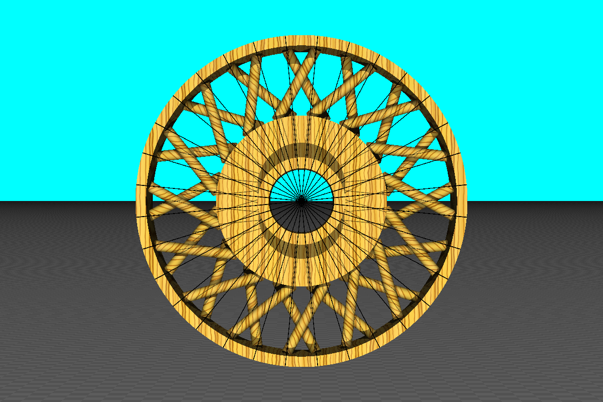
Put the large end spokes together with the small end spokes;

If I wanted to get real ambitious here is a 60 spoke wheel;

Next week I'll add the third dimension, calculating the angle the spokes make with the plane of the wheel.
No comments:
Post a Comment