When I designed the 3 Wheeler's wheels I did a lot of fiddling with the positioning of where the spokes go into the hub. Since this time I will be fiddling with the rim end already I decided to calculate where the spoke should go in the hub. The objective is to put the spoke as near as possible to the end of the hub without letting the hole for holding the tip of the spoke go through the end of the hub.
In the following picture the black coordinate system is the one POVray will use when building the wheel. I also added a second set of coordinates in red to make life easier while calculating the y coordinates of the ends of the spokes. The red system's y-axis goes through the point where a spoke enters the hub, like we calculated last week. The whole system is rotated so the x-axis crosses the point where the spoke enters the rim, also calculated last week. Then the coordinates are shifted up or down in the y direction as required to have the x-axis enter the rim at the same point the topside of the spoke enters the hub. We use the side of the spoke here not its centre line as the side will be first to reach the end of the hub.
Here is a cut-away to show how the red coordinates line up with the spoke.

What I want to calculate is the angle between the spoke and the x-axis.
I know the distance from the origin to where the x-axis enters the rim, apply the Pythagorean theorem to the points calculated last week. Call it d.
I will set the depth of the hole in the hub for the tip of the spoke. Call it t.
And for each run I will enter the y coordinate for where the top side of the spoke enters the rim. Then the distance from the origin up the y-axis to the top of the hub is one half the distance between the ends of the hub minus the input value of y for the spoke at the rim. Call it h.
The next diagram takes the x-y plane from the red coordinates in the cut-away diagram and adds in a short segment of the line across the end of the hub, line y = h, and the line along the top side of the spoke, line ACB. Under it is the derivation of a trigonometric formula for the angle of the spoke.

I labeled the picture of the wheel with the points in the geometry diagram.
A - is on the inside of the rim where the top of the spoke enters the rim
B - is on the face of end of the hub where the spoke would break out of the hub
D - is at the outer circumference on the end of the hub
C - is on the side of the hub where the top of the spoke enters the hub
O - is on the side of the hub, its distance from the end of the hub is variable as I try different amounts of cross over between the outside and inside sets of spokes. It is input as the y coordinate in the POVray coordinates where the top side of the spoke enters the rim.
The distance from O to A we have from last week's work. We calculated the coordinates of the spoke's end points on the plane, use the Pythagorean theorem to calculate the distance, 'd', between them.
d = SQRT((Xrim - Xhub)^2 + (Zrim - Zhub)^2)
The distance from O to D is one half the hub length minus the y coordinate of the offset at the rim. If the offset is to -1/8" and the hub is 1/2" long then this height , h = 1/2 * 1/2 -(-1/8) = 3/8".
The distance B to C, t, is set to 1/32".
What I'm after is the angle OAC which will also be needed in designing the jig for drilling the spoke holes. I think I've broken down the steps fine enough in the diagram for you to follow how I got my formula for the angle. Lets rename angle OAC as just 'a' so the formula reads:
d * tan(a) + t * sin(a) - h = 0
I poked around on http://mathworld.wolfram.com and some other math sites for a solution to this equation but trigonometric equations do not often have easy solutions. This was not one of the easy ones. Having been programming computers for over 40 years I thought of building a binary search program, but in case there was something better I asked for help on the Google group mog-group. Brent Meeker responded with two possibilities. The first idea involved using some trigonometric transformations to eliminate the tan(a) and turn this equation into a quartic equation in sin(a). After looking at the Wolfram site's instructions for solving a quartic equation I had to agree with Brent that this is not the way to do it. His better idea is an iterative approach called, fixed point iteration.
Starting with the fact that tan(a) = sin(a)/cos(a) Brent reworked my formula to calculate the error in a guess of the answer. Here I just paste his explanation.
Instead guess a value of a and solve for the amount of error e in your guess. First multiply thru by cos so you have
d*sin(a) - h*cos(a) + t*sin(a)cos(a) =0
or using a trig identity
d*sin(a) - h*cos(a) + 0.5*t*sin(2a) =0
Then substitute in your guess which is (a-e)
d*sin(a-e) - h*cos(a-e) + 0.5*t*sin(2a-2e) =0
or using trig identities
d*[sin(a)cos(-e)+cos(a)sin(-e)] - h*[cos(a)cos(-e)-sin(a)sin(-e)] +
0.5*t*[sin(2a)cos(-2e)+sin(-2e)cos(2a)]=0
And then here's the payoff. For small angles e, sin(e)=e and cos(e)=1. So you assume you're close and e is small so the above equation becomes
d*[sin(a) -e*cos(a)] - h*[cos(a)+e*sin(a)] + 0.5*t*[sin(2a)-2e*cos(2a)]=0
Which you easily solve for e.
e={d*sin(a) - h*cos(a) + 0.5*t*sin(2a)}/{cos(a) + h*sin(a) +t*cos(2a)}
You add this value to your estimate, which was a-e, and you will have a new value much closer to the true value of a. Take this new value as a new guess and repeat the above calculation of a new e. This should converge very quickly to as much accuracy as you need.
I tried this in a spreadsheet with d = 0.5, h = 0.35, t = 0.03, and a first guess of 45 degrees. But I found I needed to subtract e from the guess not add, maybe because POVray's angles turn backwards to the mathematical convention.
a e
45 17.8768435793
27.1231564207 2.2868135347
24.836342886 0.4709482886
24.3653945974 0.0993094122
It homed in to greater accuracy than any protractor I have in just 4 steps. And it can be coded in a simple while loop containing just two lines of code.
Now that I have the angle a, we can find the point C, it is t * sin(a) in from the end of the hub. But to draw this spoke we need its centre line, line AC is on the side of the spoke.
Adding the spoke centre line to the diagram we can calculate how far it is down to the centre.

The centre line is {Spoke Radius / cos(a)} below the line AC.
Now we can calculate POVray's Y coordinates for the spoke. At the hub it will be
Yhub = 0.5 * Hub Width - t * sin(a) - Spoke Radius / cos(a)
At the rim it will be
Yrim = The input Offset from Centre - Spoke Radius / cos(a)
Of course the spokes on the other side of the hub will have some signs changed. At the hub it will be
Yhub = -0.5 * Hub Width + t * sin(a) + Spoke Radius / cos(a)
and at the rim
Yrim = The input Offset from Centre + Spoke Radius / cos(a)
Now we have the x, y, and z coordinates for the ends of the outer sets of spokes. The inner sets which cross behind the outer ones will have the same angle to the plane of the wheel as their pair mates. To avoid hitting their mates they must be inset by at least:
Spoke Diameter / cos(a)
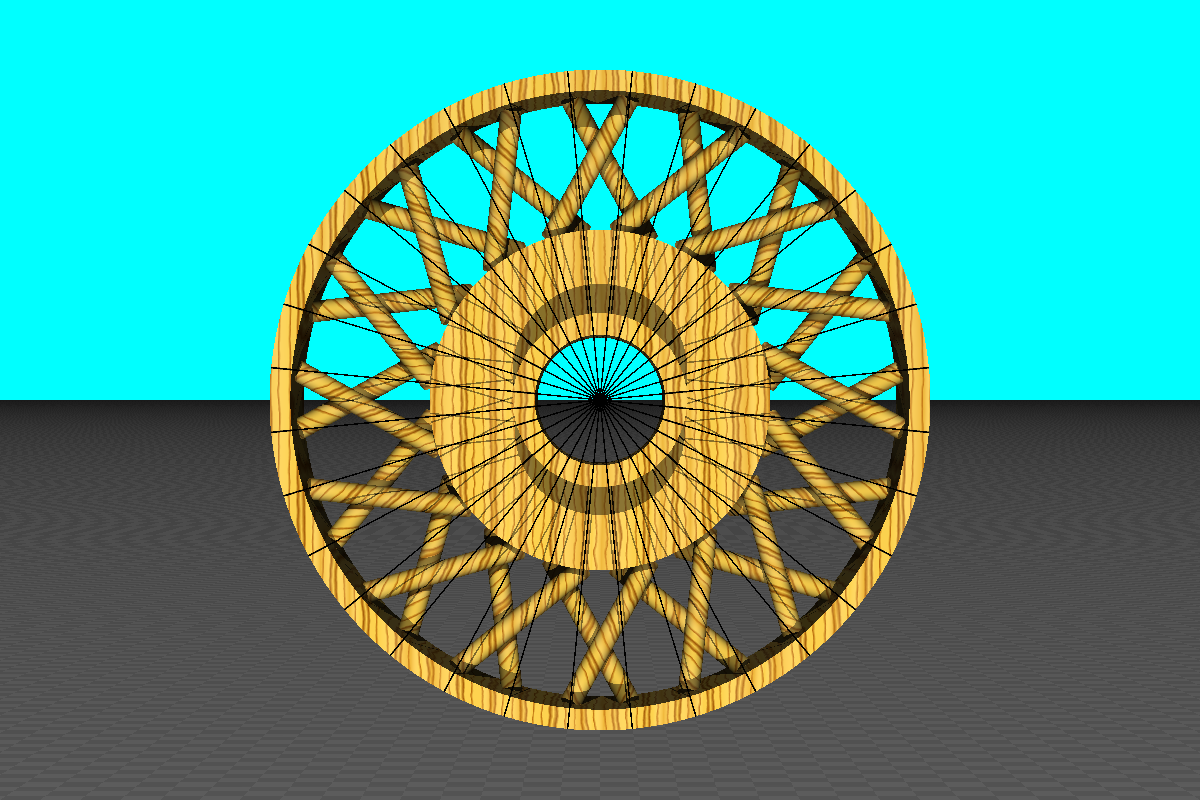
This amount works OK for the spokes on the narrow end with their shallow angle but I had to increase the inset on the other end's more steeply angled spokes, 1.1 times did the trick. POVray's intersect function clearly shows where any spokes intersect. After playing with the offsets at the rim to get no intersect pieces showing I removed the intersect function to make the following stereoscopic picture of the wheel.
Look through this picture to merge the images and get the 3D effect. It may help to thumb your nose at the picture so each eye see only the image on its side and/or shrink the picture's window a little.

I see I will have to bevel the corner where the hub widens so the spokes from the narrow end can clear it.