Showing posts with label Morgan. Show all posts

Sunday, 10 February 2013

Wooden Trike World Tour

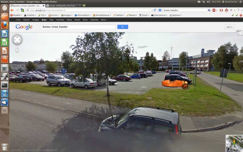
I installed a statistics package on the MSCCC web site back in December. One of the curious things I learned from it is that the build of the new Morgan three wheeler model attracts a lot of attention from all around the globe. Roughly every other day someone looks at a couple of pages or more. I decided to take a look at their towns with Google Street View. So here is my thank you for all the interest in the model trike.

Andover Massachusetts:
If any of you do build a model please send pictures and I'll add a gallery page to the series on the trike.
http://morgansportscarclubofcanada.com/New3WheelerIndex.php
Send pictures to morgansportscarclubofcanada@gmail.com

Sunday, 13 January 2013

Designing Wooden Model Wire Wheels (Part 2)

The wire wheels that I see on Morgans have the spokes that attach to opposite ends of the hub cross between each other before they attach to the rim. This is a little more complex than the motorcycle style wheels I made for the 3 Wheeler model (http://morgansportscarclubofcanada.com/New3WheelerIndex.php) where all the spokes attach to the rim along its centre line. In my POVray model for designing the wheel I'll put in a value to set how far from and to which side of the centre line the spokes will attach to the rim.

When I designed the 3 Wheeler's wheels I did a lot of fiddling with the positioning of where the spokes go into the hub.  Since this time I will be fiddling with the rim end already I decided to calculate where the spoke should go in the hub.  The objective is to put the spoke as near as possible to the end of the hub without letting the hole for holding the tip of the spoke go through the end of the hub. 

In the following picture the black coordinate system is the one POVray will use when building the wheel.  I also added a second set of coordinates in red to make life easier while calculating the y coordinates of the ends of the spokes.  The red system's y-axis goes through the point where a spoke enters the hub, like we calculated last week.  The whole system is rotated so the x-axis crosses the point where the spoke enters the rim, also calculated last week.  Then the coordinates are shifted up or down in the y direction as required to have the x-axis enter the rim at the same point the topside of the spoke enters the hub.  We use the side of the spoke here not its centre line as the side will be first to reach the end of the hub.


Here is a cut-away to show how the red coordinates line up with the spoke.


What I want to calculate is the angle between the spoke and the x-axis.

I know the distance from the origin to where the x-axis enters the rim, apply the Pythagorean theorem to the points calculated last week.  Call it d.

I will set the depth of the hole in the hub for the tip of the spoke.  Call it t.

And for each run I will enter the y coordinate for where the top side of the spoke enters the rim.  Then the distance from the origin up the y-axis to the top of the hub is one half the distance between the ends of the hub minus the input value of y for the spoke at the rim.  Call it h.

The next diagram takes the x-y plane from the red coordinates in the cut-away diagram and adds in a short segment of the line across the end of the hub, line y = h, and the line along the top side of the spoke, line ACB.  Under it is the derivation of a trigonometric formula for the angle of the spoke.


I labeled the picture of the wheel with the points in the geometry diagram.

A - is on the inside of the rim where the top of the spoke enters the rim
B - is on the face of end of the hub where the spoke would break out of the hub
D - is at the outer circumference on the end of the hub
C - is on the side of the hub where the top of the spoke enters the hub
O - is on the side of the hub, its distance from the end of the hub is variable as I try different amounts of cross over between the outside and inside sets of spokes.  It is input as the y coordinate in the POVray coordinates where the top side of the spoke enters the rim.

The distance from O to A we have from last week's work.  We calculated the coordinates of the spoke's end points on the plane, use the Pythagorean theorem to calculate the distance, 'd', between them.
  d = SQRT((Xrim - Xhub)^2 + (Zrim - Zhub)^2)

The distance from O to D is one half the hub length minus the y coordinate of the offset at the rim.  If the offset is to -1/8" and the hub is 1/2" long then this height , h = 1/2 * 1/2 -(-1/8) = 3/8".

The distance B to C, t, is set to 1/32".

What I'm after is the angle OAC which will also be needed in designing the jig for drilling the spoke holes.  I think I've broken down the steps fine enough in the diagram for you to follow how I got my formula for the angle.  Lets rename angle OAC as just 'a' so the formula reads:

    d * tan(a) + t * sin(a) - h = 0

I poked around on http://mathworld.wolfram.com and some other math sites for a solution to this equation but trigonometric equations do not often have easy solutions.  This was not one of the easy ones.  Having been programming computers for over 40 years I thought of building a binary search program, but in case there was something better I asked for help on the Google group mog-group.  Brent Meeker responded with two possibilities.  The first idea involved using some trigonometric transformations to eliminate the tan(a) and turn this equation into a quartic equation in sin(a).  After looking at the Wolfram site's instructions for solving a quartic equation I had to agree with Brent that this is not the way to do it.  His better idea is an iterative approach called, fixed point iteration. 

Starting with the fact that tan(a) = sin(a)/cos(a) Brent reworked my formula to calculate the error in a guess of the answer.  Here I just paste his explanation.

Instead guess a value of a and solve for the amount of error e in your guess. First multiply thru by cos so you have

d*sin(a) - h*cos(a) + t*sin(a)cos(a) =0

or using a trig identity

d*sin(a) - h*cos(a) + 0.5*t*sin(2a) =0

Then substitute in your guess which is (a-e)

d*sin(a-e) - h*cos(a-e) + 0.5*t*sin(2a-2e) =0

or using trig identities

d*[sin(a)cos(-e)+cos(a)sin(-e)] - h*[cos(a)cos(-e)-sin(a)sin(-e)] +
0.5*t*[sin(2a)cos(-2e)+sin(-2e)cos(2a)]=0

And then here's the payoff. For small angles e, sin(e)=e and cos(e)=1.  So you assume you're close and e is small so the above equation becomes

d*[sin(a) -e*cos(a)] - h*[cos(a)+e*sin(a)] + 0.5*t*[sin(2a)-2e*cos(2a)]=0

Which you easily solve for e.

e={d*sin(a) - h*cos(a) + 0.5*t*sin(2a)}/{cos(a) + h*sin(a) +t*cos(2a)}

You add this value to your estimate, which was a-e, and you will have a new value much closer to the true value of a. Take this new value as a new guess and repeat the above calculation of a new e.  This should converge very quickly to as much accuracy as you need.

I tried this in a spreadsheet with d = 0.5, h = 0.35, t = 0.03, and a first guess of 45 degrees.  But I found I needed to subtract e from the guess not add, maybe because POVray's angles turn backwards to the mathematical convention.

a                e
45               17.8768435793
27.1231564207    2.2868135347
24.836342886     0.4709482886
24.3653945974    0.0993094122


It homed in to greater accuracy than any protractor I have in just 4 steps.  And it can be coded in a simple while loop containing just two lines of code.

Now that I have the angle a, we can find the point C, it is t * sin(a) in from the end of the hub.  But to draw this spoke we need its centre line, line AC is on the side of the spoke. 

Adding the spoke centre line to the diagram we can calculate how far it is down to the centre.


The centre line is {Spoke Radius / cos(a)} below the line AC.

Now we can calculate POVray's Y coordinates for the spoke.  At the hub it will be

Yhub = 0.5 * Hub Width - t * sin(a) - Spoke Radius / cos(a)

At the rim it will be

Yrim = The input Offset from Centre - Spoke Radius / cos(a)

Of course the spokes on the other side of the hub will have some signs changed.  At the hub it will be

Yhub = -0.5 * Hub Width + t * sin(a) + Spoke Radius / cos(a)

and at the rim

Yrim = The input Offset from Centre + Spoke Radius / cos(a)

Now we have the x, y, and z coordinates for the ends of the outer sets of spokes.  The inner sets which cross behind the outer ones will have the same angle to the plane of the wheel as their pair mates.  To avoid hitting their mates they must be inset by at least:

 Spoke Diameter / cos(a)

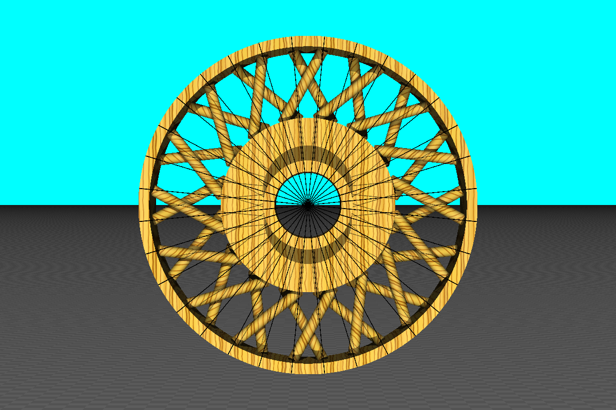
This amount works OK for the spokes on the narrow end with their shallow angle but I had to increase the inset on the other end's more steeply angled spokes, 1.1 times did the trick.  POVray's intersect function clearly shows where any spokes intersect.  After playing with the offsets at the rim to get no intersect pieces showing I removed the intersect function to make the following stereoscopic picture of the wheel.

Look through this picture to merge the images and get the 3D effect.  It may help to thumb your nose at the picture so each eye see only the image on its side and/or shrink the picture's window a little.  


I see I will have to bevel the corner where the hub widens so the spokes from the narrow end can clear it.




Saturday, 5 January 2013

Designing Wooden Model Wire Wheels (Part 1)

Instead of bearing down and getting done cleaning up the finish on the DHC I've been working on a design for the next set of "wire" wheels.  My daughter saw what I was doing while here visiting over Christmas and told me I should post the calculations on the blog.  So here is why I studied math in high school.

For two reasons I decided to separate the wheels from the tires in this design.  One, it lets me use a white hardwood for the wheel and a dark wood for the tires.  Two, the wider tire profile used on more recent cars would cause the spoke holes to exit the sides of the tire at a shallow angle which could made drilling awkward.  The wire wheel I chose to model has a hub with different diameters at opposite ends and twice as many spokes on the large end as on the small end.  In the POVray model I built a hub with a 3/8" diameter axle hole and scaled the rest of the hub around that hole.  The rim diameter was scaled to fit in a 2 1/2" diameter tire.


This week I'll just develop the two dimensional weaving pattern of the spokes.  The example I'm using has 48 spokes, this is the smallest number that has all the spokes angling into the hub and not just grazing the surface.

On the hub's large diameter end we have 32 spokes.  Draw 32 radii around the wheel.  To be able to use symmetry to get the second set of spokes rotate the radii one half of the angle between two adjacent radii so the x and y axes bisect the angle between radii.


On the real wire wheels each spoke on the large end of the hub crosses three other spokes from the large end before it reaches the rim.  The relatively fatter wooden spokes on the model would not fit across three others so I tried two.  Therefore, a spoke at one radius line on the hub will attach to the rim two radii away from its hub radius.


Calling the angle between two adjacent radii a, the hub radius h, and the inside rim radius i, we can calculate the end points of the spokes (Xh, Yh) at the hub and (Xr, Yr) at the rim. 
POVray has angles increase in the clockwise direction, opposite to the convention in geometry. Measuring the angle from the twelve o'clock position.

For the spoke angling up to the right:
Xh = h * sin(0.5*a)
Yh = h * cos(0.5*a)
Xr = i * sin(2.5*a)
Yr = i * cos(2.5*a)

By symmetry the ends of the spoke angling to the left are (-Xh, Yh) and (-Xr, Yr).

With the POVray model I do not need to calculate for all the spokes. I can rotate this pair around the centre to fill in the wheel.


The small end of the hub has 16 spokes and each spoke crosses one other spoke.  Therefore, the angle between these radii is two times the angle between the radii on the large end, i.e 2*a.


For the spoke angling up to the right:
Xh = h * sin(-a)
Yh = h * cos(-a)
Xr = i * sin(a)
Yr = i * cos(a)

By symmetry the ends of the spoke angling to the left are (-Xh, Yh) and (-Xr, Yr).

Rotating this pair around the wheel we get;


Put the large end spokes together with the small end spokes;


If I wanted to get real ambitious here is a 60 spoke wheel;


Next week I'll add the third dimension, calculating the angle the spokes make with the plane of the wheel.


Thursday, 27 December 2012

Virtual Morgan in Action (2D & 3D)

A couple of years ago a group of Jaguar owners invited the MSCCC to do a country drive with them.  In their first news brief about it they said we would have a chance to drive the North American Jaguar Club Slalom.  See www.jcna.com/library/slalom/index.php for details about the slalom.  Since you go through the set of pylons three times following three slightly different paths; an hour glass, a figure eight, then an oval, I figured I would need some visualization practice beforehand to avoid going off course.  It turned out that they did not include the slalom in the event but by that time I had already build a computer model of it.

I turned to POVray (http://www.povray.org/) to model the course, and then generate pictures at several spots around the course. I learned you can produce animations with POVray by using its clock function.  The clock's 'ticks' can be used to step through a list of coordinates of a path through the course.  Then I needed a car to drive the course, that took a couple of months of measuring something on my '59 +4 and then working out how to model it in POVray.  The result was two Youtube videos.  The car's speed is calculated using acceleration and panic stop figures from the December 1967 Car & Driver road test of a TR4A powered Morgan +4.  The maximum g's in cornering was set to 0.8g by an edjumacated WAG. The resultant course time of under 47 seconds is not a winner but it is respectable.

Here is a track marshal's view from between the start line and the finish.


http://youtu.be/zCyoyRImfXU

 The next one is the one for training to drive the course, a driver eye view in 3D using the Blue/Amber anaglyph coloring.  The driver is looking ahead to where the car will be in 2 seconds.  The gauges on the dash show a green one when accelerating and a red one when braking.


http://youtu.be/34YiFh9jmrs

Monday, 24 December 2012

Morgans in 3D!!!

A little automotive eye candy for Christmas.

When I was photographing the Mogs at the Britsh Car Day in Bronte Park last September the auto focus flashed a warning when I took a picture of one of the yellow Morgans in the row, so I shifted position a little and took a second.  Both turned out well and I wondered if they would make a good stereoscopic pair.  They do.  Cross your eyes slightly and you will see.  The people in the background moved a little so looking at them is a little discordant.


 If you have trouble getting the effect in the above picture, get two cards or envelopes. Hold a card in each hand.  Hold the right hand card so it blocks your right eye's view of the right hand image but you can see the left image OK.  Hold up the left card beside the right so it blocks the left eye's view of the left image.  Now adjust the cards so each eye can still see the opposite side image.  Now look at the middle of the gap between the cards, this will cause the screen images to merge.  Pick a spot in the image, like the windscreen pillar or a head light, and try to get the two images of that spot to overlap exactly. You may need to tilt you head at little to one side or the other to get the images to line up. Your eyes should come into focus on the screen image in a few seconds.

Otherwise:
If you have a pair of the common red/blue 3D glasses:


Or a pair of the blue/amber 3D glasses the CBC was giving away a couple of years ago for their 3D show about Queen Elizabeth II.


I know that this isn't a Morgan but its owner Al Sands is a Morgan owner, so here is his Cadillac powered Allard in 3D:


Red/Blue anaglyph


Blue/Amber anaglyph


Friday, 7 December 2012

Wooden Morgan: 1950 DHC - Week 15

This will wrap it up for my weekly progress reports.  It looks like I'll be spending the next few weeks trying to get the finish looking good.  I'm getting a lot of hazy areas and not just in the corners where I've learned to expect it with tung oil.


Al suggested I should not be applying the tung oil with a brush, as that puts on too much.  So I am applying it now with pieces of felt from a buffing disk, focusing on just the front right wing.  The haze there is thinning.  The vertical face of the wing had a hazy patch just behind the wheel well which is gone now after four days, but at this rate it will take a week or more to remove the haze from all of the wing.  The whole job will likely take until the new year.

Now with this only taking 15 to 20 minutes of my time each day, I have several ideas percolating through my brain for the next project. 
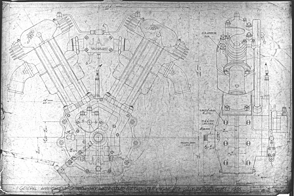
< Another 3 wheeler, barrel back with Matchless or JAP engine.


< Or the rare one, a +4+

 (thanks for the picture JHSII)

< My 1959 +4 with the high body style.  I have a virtual model:


(If you have a pair of blue/amber(or yellow) 3D glasses this is a stereoscopic picture.)

< Revisit the +8 with wider 40 spoke wheels:


< 4 seater

< Use some different coloured woods, vera wood can get a green colour when exposed to sun light. i.e. BRG without paint.
http://www.hobbithouseinc.com/personal/woodpics/verawood.htm
Or two tone...
.
.
.
So many Morgans to choose from.


Thursday, 29 November 2012

Wooden Morgan: 1950 DHC - Week 14

Almost time to glue it together.  I spent the afternoon working out how to assemble the spare tires.  With those staying in place with the help of a little double sided tape I went on to the headlights.  I cut the mounting bar to length and taped it to the underside of the wings.  Why stop there?  I decided to put on the wheels and take some pictures.


If anyone has comments, members of the MSCCC can ask the webmaster at
morgansportscarclubofcanada@gmail.com for an invitation to become a blog contributor.   That will allow you to comment on postings as you please.  Others can email the webmaster with your comments and and he will post them.